2019 Title 24 Standards
Duct Leakage Rate
Duct leakage for New installations which include * All New Equipment with 75% new ducts with all remaining ducts accessible * Cut-in’s
* 75% new ducts with all remaining ducts accessible (Duct changeout only)
are now 5% leakage rates instead of 6%
So max allowable leakage for the following sizes are; 1.5 Ton = 30 CFM2 Ton = 40 CFM2.5 Ton = 50 CFM3 Ton = 60 CFM3.5 Ton = 70 CFM4 Ton = 80 CFM5 Ton = 100 CFM As you know the 6% leakage rate was a hard enough benchmark to achieve. 5% will pose a real challenge. There will need to be quite of bit of quality control on your systems to pass. Aside from what you do now like caulk in all boot boxes, you will be required to use Duct Mastic on ALL Furnace, Coil, Plenum, and Start Collar connections. We still see duct tape and foil tape used on these connections. This tape peels off in weeks. Glenkote/Duct Mastic is required for all connections at the FAU, Coil, Plenums, AND start collars. Duct tape Cannot be used to seal Start Collars or Furnace and Coil Connections.
Filter Driers are now Required
Liquid line Filter Driers are required on ALL new installations and Condenser and Coil Changeouts. This is now part of the HERS inspection process. So if you call for a HERS inspection without a filter drier on these applications, the system will Fail Charge Testing and I will have to return at an additional cost. A photo will not be sufficient because if a drier is added after i leave, the Refrigerant Charge will have to be verified because you opened up the system.
Effective Immediately Regarding Airflow Issues
Cut ins and New Duct changeout systems that have 75% or more new duct with the remaining portions accessible require 350 CFM per ton. This 350 CFM standard hasn’t changed and can be very hard to achieve. What we thought about duct sizing before has changed quite a bit because of the huge Static Pressure drops across High Efficient evaporator coils and improperly sized and installed duct systems. The QA (Quality Assurance) Auditors who re-test us on a percentage of jobs that we complete are clamping down on this. There is zero tolerance for new systems that are Not achieving 350 CFM per ton. Raters have become extra cautious about Airflow testing, as this is the biggest discrepancy between Raters and QA Auditors. Raters have been Suspended and or completely De-Activated from ever working in the HERS field again for passing systems that don’t achieve 350 CFM per ton. Duct systems have to be designed using very large ducts on both the Supply and Return Side of the systems.
Some of the problems that we see in the field include;
Ovaled-Out return ducts
Under no circumstance can a Return Duct ever be ovalled out. YOU MUST ALWAYS FABRICATE A PLENUM THAT WILL ACCEPT A RETURN DUCT WITHOUT OVALLING IT. If a Transitional Plenum is required to prevent ovalling, one must always be fabricated.
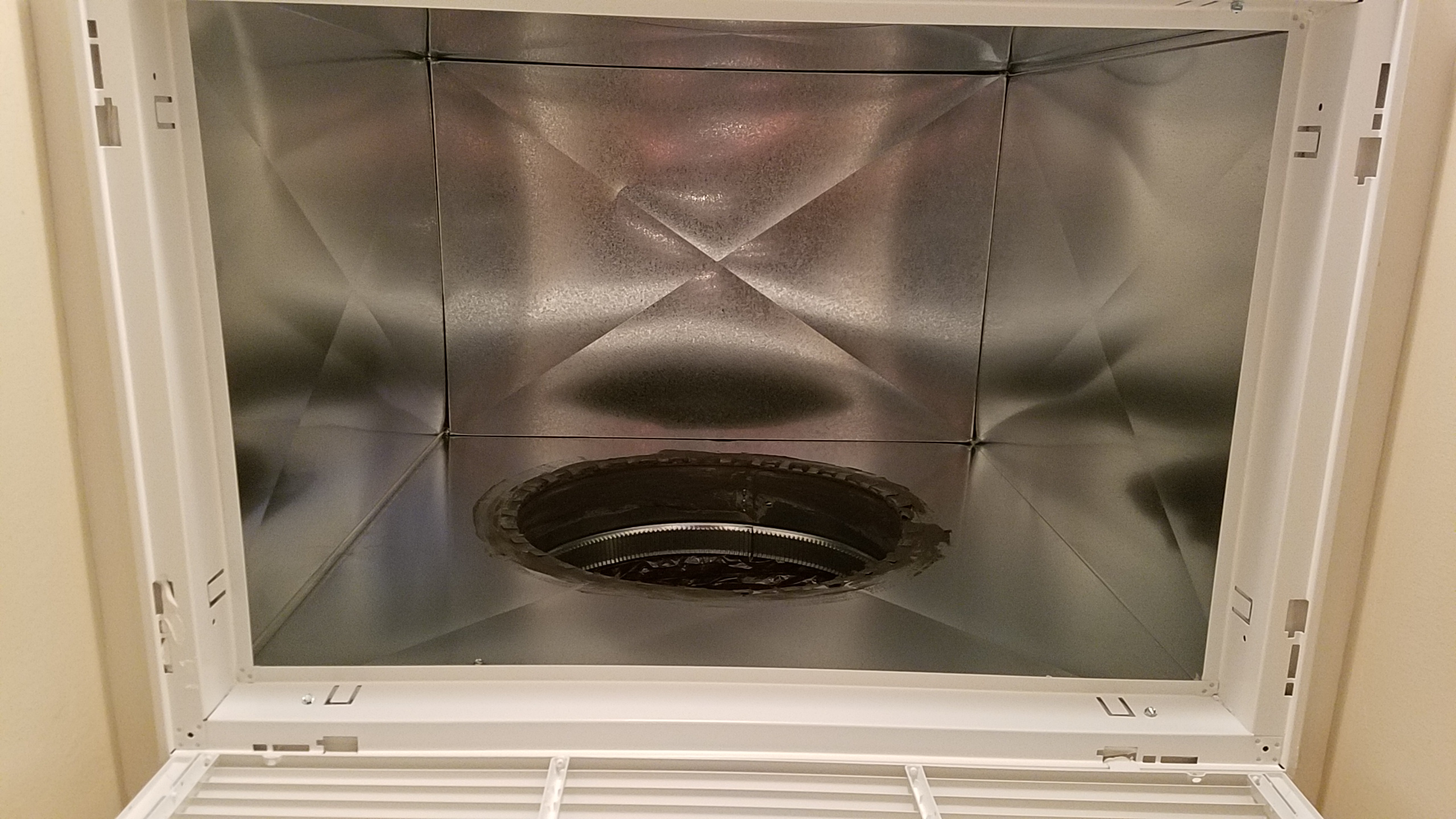
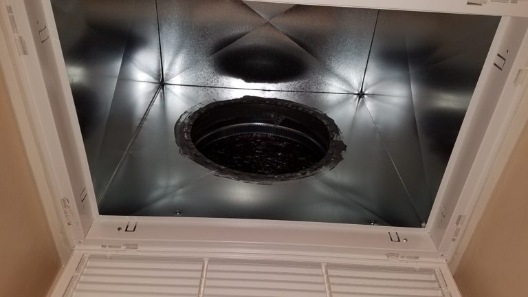
Supply House bought 3 1/2″ tall return cans
These should be outlawed from the industry. These cans create a high static pressure point between the duct opening (where you attach your return duct) and the filter. These cans put the filter grill within 2″ of the duct opening. There is not enough space between the duct opening and the filter for the air to properly mix and utilize the entire filter. Since there is not enough space between the duct connection and filter, your basically using only a portion or small percentage of the filter. That is why there is a round dark spot on the middle of these filters after use. This is a restriction. Ceiling return plenums must be fabricated taller so there is enough space between the filter and duct opening for the air to properly mix and utilize the entire square footage of the filter. Most custom installers are using 24″ to 36″ tall acoustically lined ceiling return cans and attaching the return duct into the side of the plenum. We are consistently seeing failures with systems using 3 1/2″ store bought plenums. They should no longer be used in the industry. The pictures below show a custom built return air can that greatly improves airflow and runs quieter than the short cans.
No return plenum at the FAU
We see this quite a bit and it is an automatic airflow failure. You can never attach a return duct onto a furnace without a plenum. This is a huge restriction. For example, lets say you have a 17″ 3 ton Furnace. The base of the Furnace opening is 17″ x 25″ – This equals 2.95 SF of open area. If you take a 16″ duct directly into this Furnace, without a plenum, you reduce the square footage of the furnace opening to 1.39 SF (Area of 16″ Duct). This is a difference of 1.56 square feet of space (2.95 – 1.39). This is huge restriction and will cause an airflow failure. And using just a 4″ can on the return side of the furnace is no better. Plenums must be longer and “Flare out” or Transition if necessary to accept a duct without ovalling it.
Stamped Faced Return Grills
Obviously these are very restrictive. Bar Type return grills always need to be used.
System Static Pressure
Click the link below to open the simple procedure to read and evaluate Total External Static Pressure. Installers need to get used to this. All residential Furnaces are rated at .50″ w.g (1/2″). That means that at .50″ of Total External Static Pressure, you can expect to have 400 – 450 CFM per ton in most cases according to the manufactures Fan Curve. Total External Static Pressure is the total pressure External of the Furnace on the Suction and Discharge side. You need to understand the effects that static pressure has on your systems. The static pressure drop across most High Efficient Evap Coils can exceed .50″ w.g. This is already the Entire Static drop that the Furnace is rated for, not including plenums, filters, ductwork, ceiling cans, and grills. Most new residential systems are operating at close to 1.00″ of static pressure (this is double what the manufactures rates their units at). At 1.00″ of static, you are “off” the manufactures Fan Curve. “Off” meaning that it is so far to Right of the Fan Curve, it doesn’t even list the airflow for that drop. Most Fan Curves or Blower Performance Charts go up to .90″. At .90″ your lucky to achieve 300-325 CFM per ton. This would fail Airflow testing. To read Total External Static Pressure you must drill a 3/8″ hole in the Blower Door (Suction Side) and a 3/8″ hole in the Heat Exchanger end of the furnace a couple of inches before the Evap Coil (Discharge Side). The Suction side will give you a negative number and the Discharge Side will give you a positive number. You add these 2 numbers together After dropping the negative from the Suction reading. For Example, Suction Static of -.20″ and a Discharge of +.60″. This Equals .80″ of Total External Static Pressure, Not .40″. You drop the negative on the suction reading before adding the numbers. You then find that reading on the Manufactures Fan Curve or Blower Performance Chart. You will find this in the Installation Instructions for the Furnace. This will show you what kind of airflow you can expect to have at that Static Pressure. Most Charts will show you that you will need to be LESS Than .75″ TESP (Total External Static Pressure) to achieve 350 CFM per ton.)
The 3 Ton 14″ Furnace and Coil
This Furnace and coil setup is so restrictive, it is nearly impossible, if not impossible altogether to pass Airflow Testing. The Minimum required airflow for a new 3 ton system is 1050 CFM. I have tested these systems with 2 large return ducts with 2 large Bar Type filter grills, and unit is only capable of less than 1000 CFM. The Static Pressure Drop across a 3 ton – 14″ evaporator coil is between .50″ and .65″. This is manufactures design flaw. They simple cannot design a 3 ton coil to properly fit in a 14″ cabinet without compacting the design. This creates a huge Discharge restriction. These Furnaces and Coils should be avoided at all cost. A 3 ton – 17″ Furnace cabinet and coil should always be used on 3 ton applications.
Difference in Return Air Cabinet Square Footage for a 3 Ton 14″ and 17″ Furnace.
The return opening of a 14″ FAU is 2.43 sf (14 x 25 / 144).
The return opening of a 17″ FAU is 2.95 sf (17 x 25 / 144).
Difference of .52 sf. or (1/2 sf)
This doesn’t sound like much until you put it on paper. .52 sf or 1/2 sf equals a 8.5″ inch square duct OR a 10″ round duct. (8.5 x 8.5 / 144 = .5 sf) or (5 x 5 x 3.14 /144 = .54 sf). This is a big difference, especially when it is right at the fan inlet.
If you are concerned about the 3 ton setup, the real solution here is to use a lower BTU (4 Ton) 17″ Furnace for all 3 ton systems. If in the rare case the airflow is too high, then you have the option to lower the cooling speed. A good rule of thumb on a 4 ton setup would be to select the 20″ 4 ton Furnace and coil cabinet if space allows OR a Lower BTU 5 ton furnace.
Furnace Dip Switches for ECM Motors
This is a frustrating thing for HERS raters. Most of the time we find that the Dip Switches have not been properly adjusted to provide proper cooling airflow. Some manufactures like Carrier, ship their ECM Furnaces with the Dip Switch configuration set to 350 CFM per ton. Many installer simply do not know this. The dip switches must always be set to 400 CFM per ton for Cooling. The Carrier Infinity Model requires adjustment of 5 different dip switches (For example, Switch SW1-5 needs to be ON, SW4-3 needs to be OFF, and the 3 switches associated with SW2 need to be adjusted). A lot of these Furnaces also have a “Trim” setting. This is a setting that will give you a percentage of more airflow in High Cooling setting. Most are + 7% to +10%. These switches need to be set also for proper function, and with static pressure issues this feature is almost required to pass airflow testing. Dip Switch information is located in the Furnace Installation Instructions.
Also very important – Many installers do not connect the 24 Volt wiring at the circuit board properly. IF you are installing a Furnace with an ECM motor AND a Single Stage Condenser, you must Use the Y/Y2 Terminal NOT the Y1 terminal. Or on some Models, you need to place a jumper between Y1 and Y2 if there is No Y/Y2. If you fail to do this, the furnace will run at Low Cooling speed. Please read the Furnace Installation Manual for the proper 24 volt setup.
Duct Sizing
The Trane Ductulator numbers are more realistic when using Hard Pipe systems. Because of this, you need to upsize everything. Installed Flex Duct is constantly being pinched off, ovalled out, crushed, and bent in a hard 90 or 180 degree turns. This reduces the airflow, and most of the time drastically, of the duct size in relation to what the Trane Ductulator is showing you.
The following minimum return air sizes are recommended if not required. It is important to understand that even when installing these return sizes, it will NOT guarantee the system will pass Airflow testing of 350 CFM per ton. There are no mandatory required return air sizes set forth by the CEC (California Energy Commission) (except the Return Air Duct Design Table if a Rater is not reading Airflow or Fan Watt), however this is what is passing in the field.
1.5 Ton – 14″ Duct (14″ x 30″ Grill)
2 to 2.5 Ton – 16″ Duct (20″ x 25″ Grill)
3 Ton – 18″ Duct Minimum (20″ x 30″ Grill) A 14″ x 30″ grill is borderline and we are seeing many failures with this grill size on a 3 ton. 16″ ducts simply don’t work on 3 ton.
3.5 Ton – 18″ Duct or higher (20″ x 30″ Grill Minimum)
4 Ton – 20″ Duct (24″ x 30″ Grill) A 20″ x 30 grill is borderline and may not pass. Or multiple returns and grills.
5 Ton requires multiple returns – At least 2 (18″) with 2 (20″ x 30″) Bar Type return grills. I’m seeing 2 (20″ Ducts) on these systems now.
These sizes are assuming the ducts are run perfectly without any ovalling or hard turns.
Always USE Metal 90 degree elbows in returns where necessary. Folding the duct over at the top of a can to make a bend creates High Static pressure, because the flex duct coil bunches up at the throat of the 90, and slows the momentum of the air down.
4 Ton Upflows are recommended to use Both sides of the Furnace (Basement installations) with 2 large return ducts. Minimum 2″ filters on both sides. 1″ are too restrictive.
5 Ton Upflows are Mandatory to use Both Sides of the Furnace (Basement installations) with 2 large return ducts. Minimum 2″ filters on both sides. 1″ are too restrictive.
This is what the manufacture says you need to do.
Closet Installations require large Bar Type grills on as many sides in the hallway as you can get.
We can thank the manufactures of Evaporator Coils and improperly run flex duct for these duct sizes. Remember that this is still not guaranteed to pass Airflow. It all depends how many 90 degree turns there are in the ducts. How it is routed. How long the duct is, etc. These are factors that reduce the size of the duct. Install return ducts with the shortest path possible. Don’t run 15′ of duct where 10′ will do. I know that there will be space problems in many cases. Remember that the CEC does not care about this. New systems need to achieve 350 CFM per ton minimum no matter what or where they are installed. So if you don’t have the space you need to consider other options.
Filter Sizes
Residential Systems require 1.33 SF of Filter Per Ton. This goes by the book. You need to calculate the proper size return air Filter for the size of the system you are installing. You calculate SF by multiplying the Filter’s Length x Width / 144. For Example a 20″ x 30″ filter is 4.16 sf. (20 x 30 / 144). A 4 ton system requires 5.32 sf of filtration. So a 24″ x 30″ Filter Grill would be required. (24 x 30 /144 = 5 sf). A 3 Ton needs a 20″ x 30″. This is referencing 1″ filters. Check with the manufacturer of Air Cleaners (4″ or thicker) to make sure they are capable of handling the required airflow.
Refrigerant Charging
Under no circumstances are HERS raters allowed to adjust the charge of a system in order to get it to pass. Part of the QA process is the Auditors questioning Homeowners if they see HERS raters carrying Pink bottles over to the condenser. This is literally one of the questions they ask homeowners. You must appoint a “Start-Up” guy or someone who understands Subcooling and Superheat. You must charge your systems to (+ or -) 3 degrees of the target Subcooling, and Superheat needs to fall between 4 and 25 degrees. Remember that a properly placed/mounted TXV bulb is required to pass Superheat. We still see on about 40% of our jobs, an improperly placed TXV Bulb. These bulbs are mounted on 90 degree fittings, on a weld, or are un-insulated. In most cases this creates a “Flooded Coil” or Zero Superheat. Remember to remove the bulbs on an ADP coils. They are mounted inside of the cabinet for shipping and need to be pulled out, properly placed, and insulated. Bulbs needs to be mounted on clean smooth copper so it makes good contact with the suction line. You must also follow the manufacturers position requirements.